The pcd end mill cutter is an essential cutting tool for machining processes. This hardworking tool is composed of three major pieces: a body usually crafted from high-speed steel or carbide, a shank designed to fit into the chuck of the machine tool, and a cutting edge doing all the hard work through precision slicing.
When it comes to PCD end mills, the two most popular types are solid-carbide and indexable cutters. Although solid-carbide cutters cost a bit more, they are capable of working at blazing speeds without losing their integrity even when exposed to high temperatures. Indexable cutters may be more economical, yet their less-enduring nature can be limiting.
Taking into consideration the material being processed, as well as speed and feed rates necessary, the selection of the optimal cutting tool needs to be made.
Picking the ideal pcd end mill cutter for the job is your first step to success. See to it that the cutter’s diameter precisely matches the hole you intend to drill; plus, its cutting edge should slightly exceed the depth of said hole.
To proceed, the item to be worked on must be held firmly in place; this might involve attaching it to a workbench with a clamp or gripping it in a vise. Subsequently, adjust the cutting edge of the drill so that its centre is in alignment with the centre of the intended hole.
The cutter is firmly mounted into the workpiece holder of the apparatus, after which the motor speed and feed speed are configured contingent on the material being shaped and the profundity of the cavity.
The drill should be carefully descended into the material, maintaining the same depth as desired for the hole. Once the instrument has been completely engulfed within the workpiece, extract it carefully and repeat the process until finished.
Once the hole is drilled, the cutter is unhooked from the chuck, and the workpiece is released from the vise, or fastened to the worktable. The subsequent action is to deburr the hole, for which a countersink bit is used.
After fixing the workpiece in the vise or attaching it to the workbench, the countersink bit is fit snugly into the chuck. Subsequently, its operational speeds and progress rates are modulated according to the type of material due to be machined.
After carefully positioning the countersink bit, the next step is to plunge it into the workpiece. Taking care to ensure that the sink is sunk in to the same depth of the desired hole, retract it lightly and repeat the process.
The workpiece is then detached from the vice or restringently affixed to the workbench. As the next step, it’s imperative to clean the pierced hole. To do that, a drill bit of equivalent size should be used for efficient and precise results.
The drill bit is fastened into the chuck as the material being machined is fixed by a vise or clamped onto the worktable. After that, the spindle speed and feed rate are adjusted in accordance with the characteristics of said material.
The drill bit is firmly slipped into the material being worked upon, with the level of its insert running as deep as the required finished hole. A subsequent retraction will then take place, completing one independent iteration.
After wiping down the hole, it’s time to free the workpiece from either the grips of the clamp or the table. Inspecting the opening is a must and can be achieved by utilizing a magnifying glass for close-up inspection.
To ensure a smooth finish, any burrs or jagged edges should be worked out of the hole before proceeding. If not, the material should be held back in the clamps and the operation carried out again.
Related Product
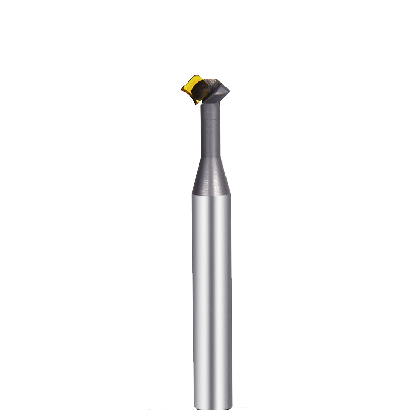
MCD Turning Tool Mirrow Finish R Cutter
Product Information Product Name Single Crystal Diamond Lower Chamfering Inner R Cutter Brand MSK Handle Material Tungsten Steel Blade Material Customized Pcd, Single Crysta […]
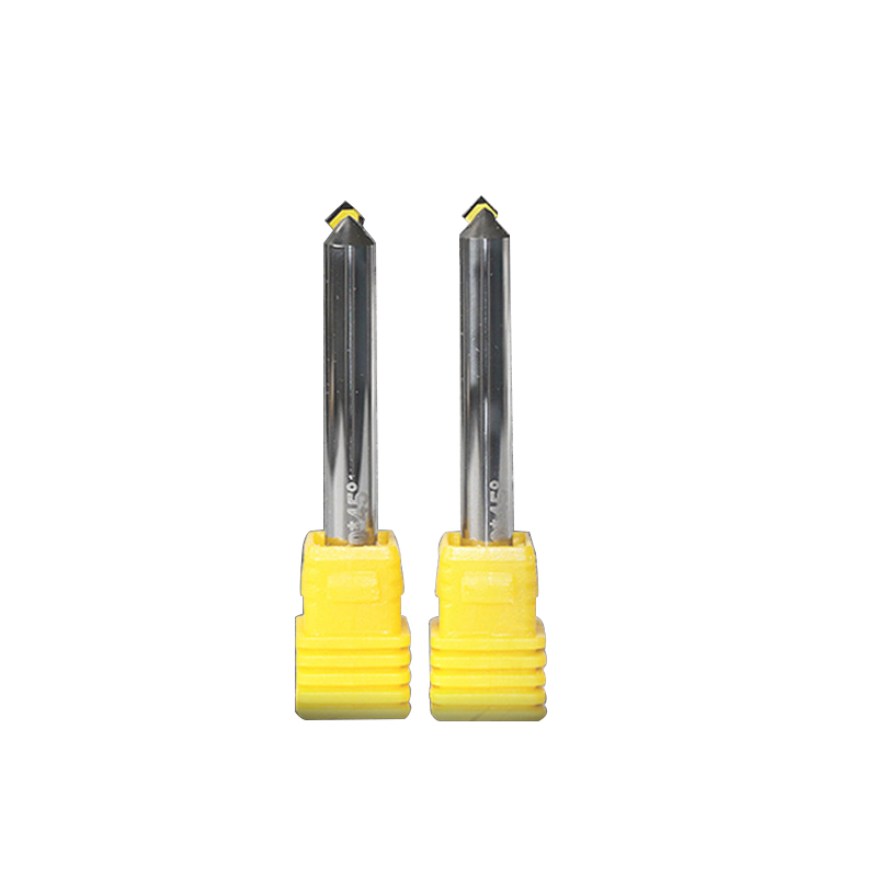
MCD Polishing Cutter for Gold Silver
Product Information Origin Tianjing, China Whether To Coat Uncoated Brand MSK Unit Weight 0.3kg Tool material Tungsten steel bar imported from Germany Product Size Shank Dia […]
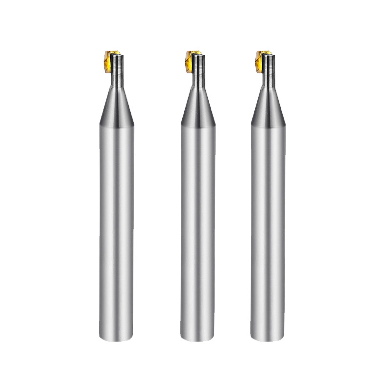
Diamond Turning Tools Outer Jewelry R Cutter
Product Information Origin Tianjing, China Material Tungsten Steel Brand Msk Type Half Round Key Milling Cutter Product Name Single Crystal Diamond Side Edge Arc Milling Cut […]
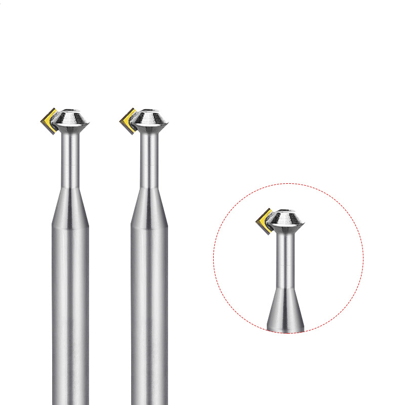
MCD High Gloss Chamfer Cutter For Gold
Product Information Origin Tianjing, China Type Flat Milling Cutter Brand Msk Whether To Coat Uncoated Series Cutter Milling Cutter Processing Range Clocks And Watches, Copp […]
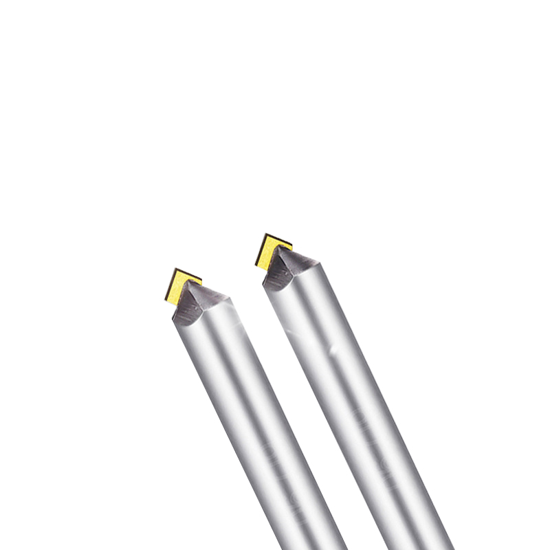
Lathe Bits MCD High Gloss Chamfer Tool
Product Information Origin Tianjing, China Cutting Edge Form Straight Edge Brand MSK Material Single Crystal Diamond Chamfer Angle 30°-180° Type Angle Milling Cutter Minimum […]
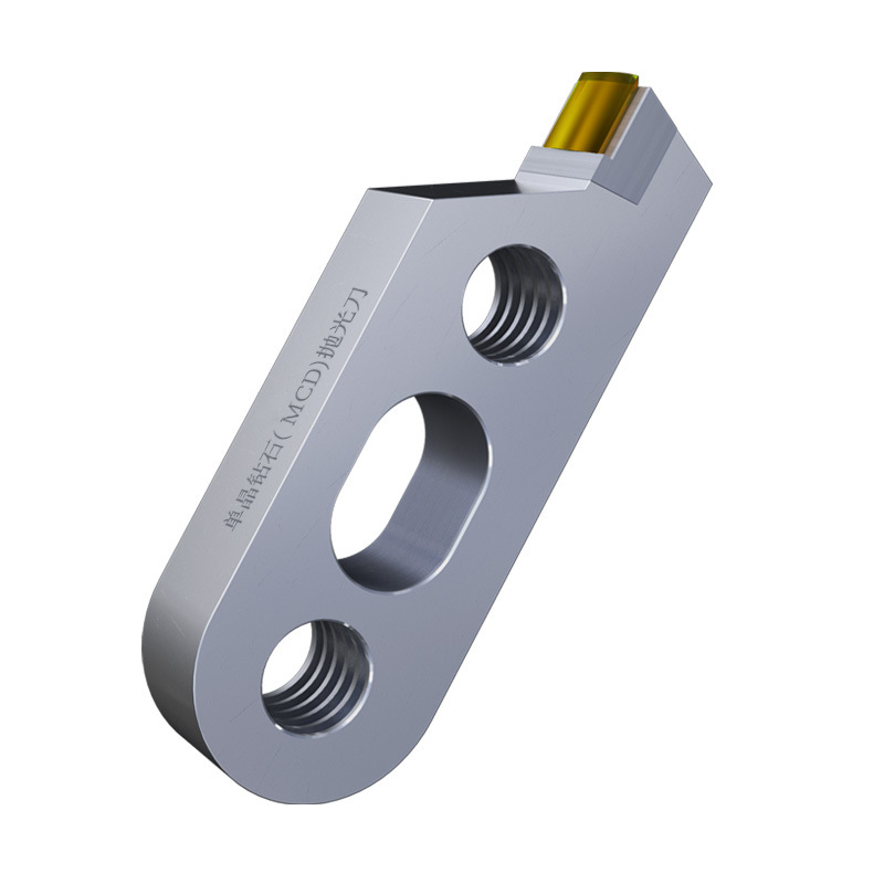
Single Crystal Diamond Polishing Cutter
Origin Tianjing, China Shank Diameter 6 (mm) Brand MSK Blade Change Method The Diamond Is Welded To The Cutter Body As A Whole Material Single Crystal Diamond (MCD) Scope Of […]
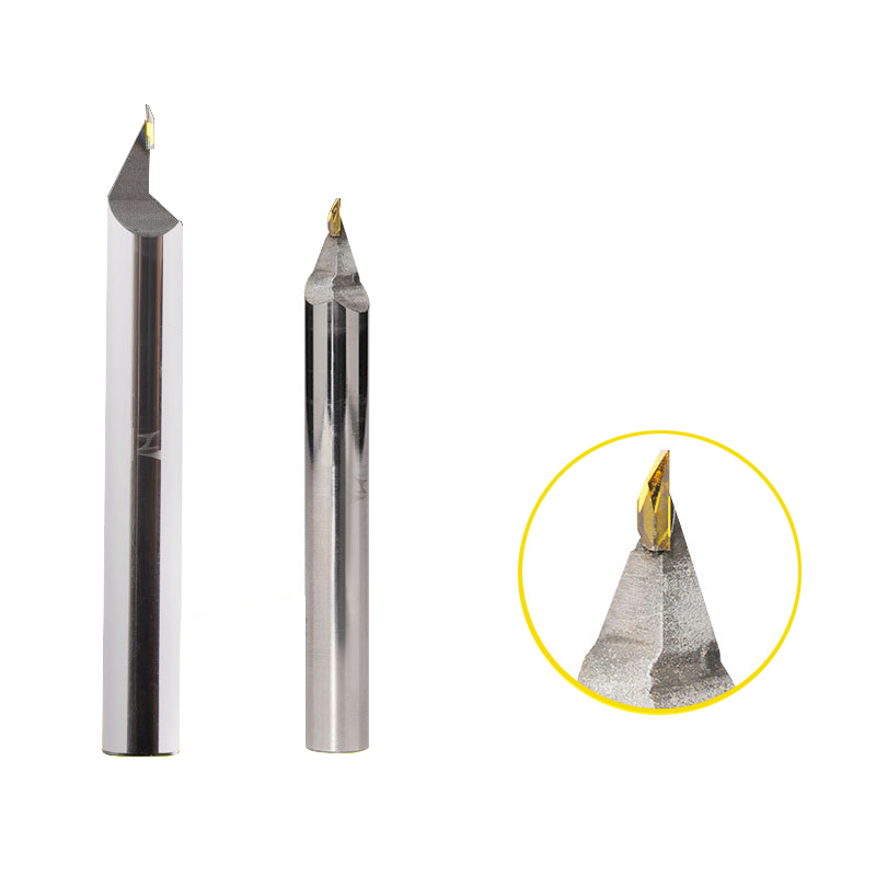
CVD/PVD/MCD Gold Jewelry Diamond Engraving Cutter
Parameter Product Name Single Crystal Diamond Carving Cutter Rotating Speed 10000-30000r/min Tool Nose Width 0.1-6.0mm Feed 1500-5000mm/min Blade Material Single Crystal Dia […]
Post time: 2023-07-05


